
The design and installation of key components for large plants requires expert co-operation between all participants (example: Hightemperature gas turbine with downstream fabric expansion joint to compensate for thermal expansion and settling due to particular geological conditions)
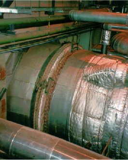
First-time use of a fabric expansion joint between the GT outlet
and diffuser in a SIEMENS V94.3
| Expansion joint supplier: | DEKOMTE GmbH |
| System supplier: | SIEMENS AG |
1. Large expansion joints for gas turbines as an example of an innovative approach with regard to increasing plant performance.
Seeking out and solving tasks which represent a step forward in techno-economic progress and meet a need for innovation is a worthwhile endeavour for competent and successful businesses to undertake as part of technical diversification on the basis of a proven production program. Such innovations lead to components with a high intrinsic value. To identify unavoidable risks in development and to minimise these, DEKOMTE has introduced theoretical considerations, computer-aided calculation processes, long-term tests and operating experience in the context of a multidisciplinary design development (Fig. 1).

2. Example of an agreed co-operation between two very different companies (Siemens / DEKOMTE) in the development of large expansion joints for extraordinary stresses.
The aforementioned appraisal of innovations is based in this example on close co-operation between Siemens KWU, Erlangen and a expansion joint manufacturer, preferably for special tasks, DEKOMTE for the plant Puertollano. For the special design of the required expansion joints, the plant constructor, Siemens KWU, also contributed substantially with its specialists in defining the task and in the various stages of the solution. In the case considered here, a type V94.3 gas turbine system to be installed in Puertollano (Spain), there were particular problems due to the different geological conditions, because the plant concept chosen meant that the gas turbine and diffuser are mounted on two separate foundations. The resulting different settling rates represent additional movements which must be taken up between the gas turbine and diffuser. Geological surveys showed that an additional lateral movement of about 30 mm can also occur. This was not discovered until the construction phase and thus nofurther large design changes could be undertaken.
Such settling could, however, not be taken up by the previous-used metal expansion joints at reasonable technical cost or without involving structural modifications (Fig. 2). On the other hand, the metal expansion joints had been preferred because of the high gas temperatures. The only way in which the movements which occurred could be compensated for without changing the system design was to fit high-quality fabric expansion joints. The soft material used in a fabric expansion joint enables substantially greater expansions compared with the metals otherwise used and, unlike metal, expansion in all directions can be dealt with.
The large diameter of the special expansion joints now required should nevertheless guarantee trouble-free operation between the gas turbine and diffuser for several years.
It was only after comprehensive consultation between Siemens KWU and the supplier DEKOMTE, that Siemens KWU could be convinced to use fabric expansion joints (EJ) for this particular case. The most important advances for the fabric expansion joint were as follows:
1) Improved insulation of parts exposed to heat.
2) The special design of insulating cushion which prevents the insulating mats disintegrating or being dislodged.
3) Restrictors which prevent rapid pressure changes between the insulating cushion and bellows.
4) Double web construction, which shows a higher resistance to cyclic stresses than a L-flange-design, in conjunction with increased heat dissipation in the clamping area, particularly due to the patented DEKOMTE metal convectors.
3. Considerations on the replacement of the previously-proven large metal expansion joints by a fabric expansion joint for the plant Puertollano whose functional efficiency had meanwhile improved due to technical progress
To have used a metal expansion joint would have meant an expensive, complicated, and therefore unreliable, adjusting mechanism would have had to have been provided to compensate for the anticipated ground settling, to prevent overstressing the components (Fig. 3).
The solution by using hitherto unusual structural elements was demonstrated, on the basis of his experience and ideas, by Günther de Temple, manager of the expansion joint manufacturer DEKOMTE, at a presentation arranged in Siemens KWU, Erlangen. The revolutionary and futuristic core of his design was the replacement of the metal expansion joint by a soft-material fabric expansion joint (EJ). This proposal was based on the following main points:
1.) The cooling of the critical bellows clamping areas was improved. Cooling is achieved by the free convection of outside air, which flows over metal wings (patented DEKOMTE convectors). They dissipate the heat from the particularly heat-susceptible bellows clamping area between two flanges.
2.) The steel structure shown for the plant Puertollano (base load station with smaller starting cycles and smaller load-transients) is able to withstand the thermal shock which occurs over a period of approximately 20 years.
3.) The axial and lateral movements which occur present no great problems when fabric expansion joints are used.
4.) The speaker could show convincingly that new fabric expansion joints (fig. 4) are capable of withstanding extraordinarily-large earth settlements in the pipe system of the GT system without damage, over the desired malfunction-free operating period (50.000 h).
5.) Even without knowing of the urgent requirement in Puertollano, DEKOMTE had already for a long time been carefully studying the behaviour of fabric expansion joints, as their availability was increasingly proving the determining factor (fig. 1).
The surprising proposal by de Temple initially met with scepticism, but the solution was specifically tailored for the conditions of the site of the GT system at Puertollano.
As a result of the presentation, Siemens KWU decided to hand over the construction of the expansion joint sections in the pipe and duct system to DEKOMTE.
4. Division of tasks between the client and supplier for optimisation of the planned procedure, based on the experience of both partners
The remarkable thing about the plant Puertollano is that for the first time worldwide a fabric expansion joint is to be installed in a Siemens GT system. This was based on an exhaust gas temperature downstream of the GT of up to 650°C, combined with the thermal shock inherent in the system. In addition to these thermal stresses, extraordinary mechanical stresses occur due to the flow behaviour.
At full load, flow velocities of up to 130m/s occur. These maximum velocities are measured on the outer edge of the duct crosssection, and thus are located in the area in which the expansion joint is fitted. In addition to the operating parameters which have to a large extent been checked, additional stresses also have to be taken into account. These could not be clearly specified. This situation was not unusual for DEKOMTE and had already been taken earlier as an incentive to use observations and long-term experience to make qualified estimates, i.e. for unexpected, intensified operating stresses over an operating time of approximately 90.000 hours. Such records have recently become available in the form of FPC% (failure probability percentage curves) (fig. 5).
Compared with the previous assumptions, they represent a more reliable design basis. It has been possible in recent years to substantially improve such graphical representations by careful observation. The FPC% method produces a systematically improved approximation to reality, because the designed and actual events can be continuously compared with previous events, including possible
faults, which have been unambiguously, personally documented. Experience has shown that the availability of fabric expansion joints also depends on the precision of the installation work, because this generates higher strain stresses.
This meant that the strain capacity was substantially restricted by the magnitude of the movement and its direction. The efficiency, taking account of installation costs, of different designs of expansion joints from very di ferent materials was made clear by the illustration produced by Allianz, the industrial insurer (Fig. 12). The installation of the high performance expansion joint involved tasks both for the system constructor Siemens and for the expansion joint supplier DEKOMTE. This demanded close cooperation in order to find a solution which was best from the techno-economic viewpoint. The resulting tasks can be seen from an overview of the expansion joint parts and services provided by DEKOMTE. The experience available at DEKOMTE was confirmed by mathematical, computer-aided verifications.
4.1 Temperature and stress analysis with the aid of an FEM calculation
A temperature ad stress analysis was carried out using the design data (Fig. 3) and the start-up curves (Fig. 7).
Fig. 8 shows the different node temperatures over time. It can be seen that the temperature in the clamping area is distinctly below 200°C because of the function of the convectors. This low temperature in the clamping area guarantees a high safety reserve for the sealing layers of the expansion joint. Furthermore, no large temperature difference builds up between points 3 and 6, and thus no excessive thermal stresses can occur.
Fig. 9 – 14 show the temperature map and stresses at various time points. An analysis of the determined stress by means of the low cycle diagram (Fig. 15) showed that approximately 7000 cycles are permissible.
A DEKOMTE FPC (Fig. 5) for the failure probability over many years operation was also used as a particular feature.
This enabled the availabilities to be assessed better than with the documents hitherto prepared, and also the chosen design could be confirmed to a far greater extent from a techno-economic point of view by using a cost-effectiveness appraisal with reference to the curves (Fig. 16). With regard to the reliability of the pioneering fabric expansion joint, a later work by B. de Temple (Supported fabric expansion joints for the steam turbine combined block power station) was evaluated and a paper entitled:
„Functionally-capable fabric expansion joints for gas turbine systems“ was contributed to the VGBKraftwerkstechnik (VGB Power Station Engineering) journal by employees of DEKOMTE. The comprehensive collection of DEKOMTE technical literature on fabric expansion joints was also available.
This dealt comprehensively with multidisciplinary design development for an optimised product (Fig. 1) For the purposes of assured availability, the theoretical considerations were not limited to the normal operating conditions but instead were able, on the basis of practical experience over many years, to take account of the flowpressure effects, the quality and quantity of which were largely unknown. Turbulences could also be detected which indicated that critical vibration up to sympathetic vibration could be expected. Reports based on practical experience with the representative flow tests from previous GT projects show this. (Examples are shown in Fig. 17 – 20).

5. Critical appraisals of individual technical details essential to success, from the point of view of the increased stresses of the required large expansion joints
Installing a expansion joint causes a local expansion of the gascarrying cross-section. This can result in detrimental effects for the operation and the durability of the ducts. To prevent such effects as far possible, the hollow crosssections in the area of the expansion joint were to some extent bridged by duct extensions. Flowguiding elements of this kind are called guide vanes. To design them properly requires a thorough knowledge of the possible stresses and effects. As a start, it was possible on the basis of previous discussions of pressure behavior to optimize a special membraneexpansion joint for the GT system described. In doing so it had to be taken into account that the pressure at different points within the system can be substantially different at the same time point and also depends on the operating state of the gas turbine system. The fabric expansion joint was located in the downstream part of the gas flow. In the cast of the gas turbines in Puertollano, the following circumstances proved to be significant.
5.1 Guide vane excitation
Vibration GT system causes damage, particularly fractures. Vibration can be caused by periodic flow phenomena such as turbulence separation, or also by stationary irregularities in the absolute flow which acts as periodic excitation. The wake flow behind the runner blade hood of the gas turbine („wake depressions“) cause periodic excitation of the guide vane. At a fixed speed, specific frequencies can be assigned to the possible excitation caused by the relative movement of the rotor blades. At a variable speed and also when starting up and shutting down the gas turbine, the frequency ranges influence the excitation.
5.2 Guide vane resonance
Guide vanes are excited to vibration at great amplitude if the excitation lies close to a natural frequency. Guide vanes have many natural frequencies corresponding to their various modes of vibration. The alternating stress caused by vibration increases in proportion to the amplitude of the vibration. To minimize this, the resonances belonging to the lower orders of flexural vibration are to be avoided by action on the excitation sources or by the design of the guide vane. For guide vanes with a rigid clamping where there is no centrifugal field effect they can be calculated as for members restrained on one end. However, because of the difficulty in determining the elasticity of the clamping they are frequently lower. Vibration of the exhaust gas duct can also be transmitted via the clamping (coupled vibration).
5.3 Guide vane vibration of
continua
A continuum with mass has an infinite number of natural frequencies. Partial differential equations are obtained from the fundamental laws of dynamics as a motion equation. The boundary conditions are satisfied by transcendental and proper value equations. The Ralyeigh quotients and Ritz method are used as a basis for approximate solutions. Siemens KWU were able to make a substantial technical contribution in this field.
5.4 Flexural vibration of struts
(Fig. 21)
Borrowing from the relevant literature, Fig. 20 shows the pressure conditions to be expected in the combined cycle (gas and steam mode) and simple cycle (bypass mode). An additional extreme requirement for the fabric expansion joint was that the flow velocity pertaining at the installation site can be three times the value of the „normal“ velocities in the exhaust gas section and thus the pressure fluctuations due to flow separation can also rise from 9 mbar to approximately 27 mbar. Superimposing the static pressure at the installation site on this pressure fluctuation therefore results in the following:
| · | Simple cycle |
| -5 mbar static | |
| +29 mbar dynamic | |
| · | Combined cycle |
| +13 mbar static | |
| +29 mbar dynamic |
i.e. situations such as those shown in Fig. 22 can occur. Furthermore, the expert fabric expansion joint manufacturer assessed the following operating pressures and pressure functions with regard to the technical design of a expansion joint with a long service life and high degree of availability.
| · | The pressures during start-up, i.e. the startup pressure over time. |
| · | The stationary pressure during full and partial load operations. |
| · | The pressure during shutdown, i.e. the shutdown pressure over time. |
| · | The pressure when closing and opening gate valves or damper valves for switching the bypass to the waste-heat boiler and vice versa. |
| · | Pressures and pressure surges which abruptly occur when damper valves or closure disk valves are suddenly closed. |
| · | Pressure changes which can occur due to shutdown faults, if violent deflagrations are caused. |
| · | The limitations of the flow velocities in the exhaust gas ducts. |
An understanding of the pressure behavior is particularly useful for optimizing the design of a special membraneexpansion joint, such as for the Puertollano system.
The difficulty on one hand is that the pressure in the exhaust gas duct is not necessarily the same as the pressure at the installations point of the membraneexpansion joint, and on the other hand that the
pressure depends strongly on the operating state of the gas turbine system.
In order to be able to safely operate a special fabric expansion joint in a GT system, the filling pressure, which depends solely on the internal construction or flexibility of the fabric expansion joint, must be guaranteed by the system designer or operator. Only maintaining the filling pressure steady under all operating conditions enables the fabric expansion joint to cool and deform in the intended manner.
(Extract from „Gestützte Weichstoff-Kompensatoren für Gas-Dampfturbinen-Kombi-Block- Kraftwerke“ (Supported fabric expansion joints for gas-steam turbine combined power stations)
by Prof. B. de Temple).
6. Evaluation of previous
operating time
In June 1999, DEKOMTE carried out a status analysis on site. The fabric expansion joint was visually examined and temperature measurements taken at selected points (Fig. 23). It should be noted that with regard to the measuring points selected, there was no access overall to take a sound measurement.
As expected, the fabric expansion joint had performed its function without faults, despite the adverse operating conditions which lay outside the design criteria. The values measured on site, within the context of the „Monitoring and measurement in the context of the warranty period and evaluation and comparative analysis of theory against practice“ task definition received as part of the contract, have as expected, produced results corresponding to the theoretical assumptions and statements on the basis of calculations (Fig. 8).
For a more reliable result, the necessary measurements were spread over an extraordinarily long period of approximately 3 years. The system was put into service in 1996. Since then approximately 19.580 equivalent hours have been run with the special fabric expansion joint without faults.
The equivalent operating hours are as follows
Top = 10.326 h
Tdyn = 4.628 h (340 Starts)
Täquiv.,op = Top + 2* Tdyn “ 19.580 h
Accordingly, the metal expansion joint between the gas turbine and diffuser in a station with similar conditions as in Puertollano can be replaced by a fabric expansion joint without reservation.
It offers not only the advantage of a more cost-effective investment, but also exceed the metal expansion joint with regard to resistance under very problematic operating conditions. On the basis of the proven operating capability, it can be concluded that the fabric expansion joints would also fulfill their functions in similar gas turbine systems, without special stresses.
Fabric expansion joints of this kind have been in trouble-free service for 10 years and more and have then been routinely removed (failure probability curve Fig. 5). Fig. 16 shows the costeffectiveness of the use of fabric expansion joints instead of metal expansion joints. In principle, the illustration also applies to other exhaust gas systems with compensation elements.
7. Conclusion
DEKOMTE appreciates having found the kind of logical, competent and enthusiastic business partner which is indispensable for such a demanding project, and which could be a pointer for a strong sector of the economy. DEKOMTE extends its thanks for the confidence shown in the capability and conduct of the company.

Author: Günther de Temple
© by Günther de Temple
No part of this publication may be reproduced, photocopied, duplicated or transmitted in any form or by any means, electronic or otherwise, and no part of this publication or of a copy, reproduction or
other duplicate or individual excerpts thereof, may be altered without the express written permission of the author. Any violation of this regulation will be penalised with up to three years imprisonment or a fine and can have consequences under civil law.